Python SMTP User Enumeration for Penetration Testing
Welcome back my fellow hackers! I was thinking recently, and came to the realization that we haven’t really been cooking up any homemade tools here at HackingLoops, so I’ve decided to change that. Today we’re going to be learning about SMTP user enumeration, as well as building an enumeration tool of our very own and taking things further than just using the python smtplib to send emails.
First, we’ll discuss the SMTP protocol, then we’ll follow it with the purposes and potential of this enumeration. Once we’ve covered that, we’ll discuss the methods that we can use to enumerate these users and test smtp. After all that is said and done, we’ll start constructing our own script. So, let’s get started!
The SMTP Protocol and User Enumeration
What is SMTP?
SMTP, short for Simple Mail Transfer Protocol, defines the standards used to transmit e-mail between systems. SMTP is not only used by mail servers for relaying messages to one-another, it is also used by the e-mail client of the end-user in order to transmit a message to the mail server for further relaying.
What is SMTP User Enumeration?
These SMTP servers have users registered on them, and these users have e-mail addresses. By sending probes to the server in the form of certain commands, we can tell if a given user exists. By repeating this process again and again with a list of varying usernames we may be able to identify a multitude of users or e-mail address on the target server. By verifying the existence of these users, we can then proceed to send out phishing attacks directly targeted at them.
How Does SMTP User Enumeration Work?
There are 3 commands in the SMTP protocol that we can use to enumerate a user: VRFY, EXPN, and RCPT TO. The VRFY command is short for verify, and is actually mean’t to validate usernames and addresses. Because of its innate purpose, many administrators disable the VRFY command to stop spammers. The EXPN is very similar to the VRFY command and doesn’t really require extra explaining.
The RCPT TO method is different however. First, we need to discuss the MAIL FROM command. This command identifies the source address of an e-mail being sent. Once we send a MAIL FROM command, we use RCPT TO method to identify the recipients of the e-mail. By repeating RCPT TO commands after the MAIL FROM command, and never actually finishing the started e-mail, we can identify the existence of any user we’d like. Now that we understand SMTP and SMTP user enumeration, let’s get started on building our script!
(Note: the script can be found here on Pastebin. The screenshots here do not have comments, but the Pastebin post does, so I suggest you keep it open and reference it while we go through it here.)
Building the Enumeration Script
Step 1: Beginning the Script and Initializing Class
In order to keep this simple, all our functions will be housed under a single class. Once we’ve completed these functions, we will be able to create an instance of this class and execute the functions as we need. In this step we are first going to set our interpreter path, import a module we’ll need, and initialize our class:

As you can see, we only need a single module at this point, socket. The socket module will allow us to create and utilize network connections. Our class also takes a number of arguments, these being: the target IP address, the file containing usernames to try, the port number to connect to on the target, a scan type, and an address to use if a MAIL FROM command is required (RCPT method). Also, two empty self attributes are created, self.sock will later contain the socket object that connects to the target and self.targetBanner will store the banner from the target server when we connect for the first time.
Step 2: Function to Read List of Users
Next up, we’ll be creating the function that will read the file containing the list of usernames supplied when the object was created. In our init function, we stored the path to the file in self.userlist. Using this, we can read and parse the file, after which we can store the new list in self.userlist, replacing the file path:

Since this function won’t be executed till later, our list of users will remain un-read until we call it. Once it’s called however, the list will be read and stored.
Step 3: Function for Constructing and Handling Sockets
Naturally with a script like this, we’ll be using sockets in order to make and use the connection(s) to the target server. In order to ease the implementation of these sockets, we’ll be building a pair of functions to handle their creation:
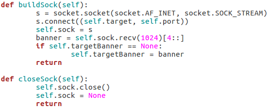
Our first function, buildSock(), follows these steps: create the socket object, connect the socket to the target IP address on the target port number, store this connected socket object in self.sock, receive the server banner, and store the server banner in self.targetBanner (if it hasn’t already been stored there). The closeSock() function is simple and not really necessary, but it does save us from repeating some lines of code later. It simply closes the socket object in self.sock and resets its value to None.
Step 4: Function for Checking Vulnerability to Scan
This function will read the type of scan that was chosen and test the target server to make sure that it’s vulnerable before the enumeration begins. We can do this by attempting to use these commands:
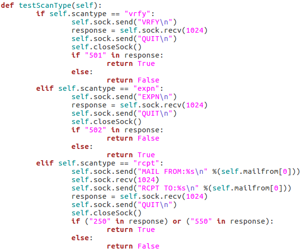
The first test is the VRFY test, which will send an empty VRFY command to the target. If the target responds with 501 (the SMTP reply code for a syntax error), then the VRFY command is available to be used. The second test will check for vulnerability to the EXPN method. This can be accomplished by sending an empty EXPN command, and if the target responds with a 502 (command not recognized) then the EXPN command will not work. The final test is for the RCPT command. We start by sending our MAIL FROM command containing the given/default username. We then send an RCPT TO command targeted at the same user. If the target responds with 250 or 550 (OK or user unknown) then the RCPT TO method is available for use.
Step 5: Functions to Probe Target for Username
These next four functions will all be related to probing the target for a given username. I’ll go ahead and throw up the screenshots, then we’ll discuss them:


These three functions all behave similarly to each-other and to the function for checking the targets vulnerability to the scan type. The commands are repeated as they were before, but this time we add the username we’d like to enumerate to the command. If the target responds to this with 250(OK) then this means that user exists (252 is also an acceptable value for the VRFY method). Finally, we have this function:
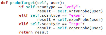
This function simply parses the string that was supplied as the scan type when the class is created and probes the target for a given username using that probe method. This will allow us to supply usernames to a single function while still probing the target using the proper method.
Step 6: Taking and Parsing Arguments
Now that all of our functions are complete, we can start putting together the body of our script. First, we’ll import some other modules and then we’ll set up and parse the arguments for the script:
 Here we can see that we have seven arguments available when using this script. Firstly, we have the target IP address and port number, then there’s the file path to the word-list containing the usernames to probe for. There is also a switch for each scan type (one of which must be supplied) and finally there is an optional flag to specify the username/e-mail address to use with the RCPT TO method.
Step 7: Detecting and Reporting Bad Input
A big problem in scripting is that invalid user input can really gum up the works. The easiest way I’ve found to combat invalid input, is to make sure you never get invalid input. We can do this by running a series of checks to make sure everything is in order before we continue. First, we’ll validate the target IP address:
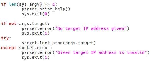
We start by checking to see if a target has even been supplied. If it hasn’t, we can raise an error through the parser to tell the user that one is required. If an address is given, we can run it through the socket.inet_aton function, which will raise an error if the IP address is invalid. Now that we’ve handled the validation of the target IP, we should move on to validating the port number:

This block of the code will check that the given port number is in the correct range of integers, if it is not, an exception is raised, and the port number is reported as invalid. The try/except block will also give this report if the int() function raises an error (a non-integer value being given). Next up we’ll check that the path for the word list is in order:

First, we make sure that a file path was given. If a file path was given, we use the os.path.isfilefunction to evaluate whether or not the file actually exists. If an existent file path was given and the checks are passed, nothing happens. Next up, we will be verifying the chosen scan type:

First, we pull all the scan type values out of the arguments and put them in a list. We then use an ifstatement to say this: if there is more than one true value or zero true values, return an error. This will allow us to filter out invalid scan type input. Now that all our checks have been completed, we can move on to executing the enumeration.
Step 8: Performing Enumeration
Now that we’re starting our enumeration, we need to create an instance of our SMTPUserEnumerator and pass all the arguments we received:

The if/elif block simply identifies the type of scan that was chosen and stores that value in scantype. Also, before we construct the enumerator object, we print back to the user: the chosen scan type, the target IP, and the target port number. Now that we have our enumerator object, we can run the testScanType() function in order to validate the targets vulnerability before we continue:

As you can see here there are three possible responses to the vulnerability check: good, bad, and fail. A good result means that the checking function returned true, a bad result is returned for false. Also, if an error is generated, the check is reported as a failure and the script exits. Now that we’ve checked the target, we can parse the list of usernames:

This is fairly self explanatory; we print that we’re parsing the list of users, then call the readUsers()function on our enumerator object. Should this process fail, the script will say so and exit. Once the usernames are read we can move on to the actual enumeration:
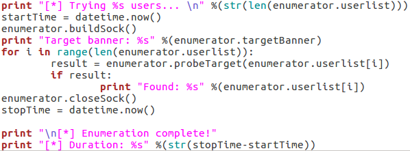
We start our final code block by printing how many usernames we need to try. Once we’ve done that, we use datetime.now() to start the clock for tracking the duration of the scan. We then call buildSock() to re-connect to the target and print the targets SMTP server banner. We then loop through the list of usernames and call the probeTarget() function for each of them. If a username is reported as good, we print it and move on.
Once the enumeration is complete, we call the closeSock() function and stop the clock for the duration. We then print that the scan is complete and print the difference between the two time values we took (resulting in the elapsed time from start to stop). Now that our script is complete, there’s only one thing left to do!
Step 9: Test the Script
We’ll be testing our script against a Postfix ESMTP server running on an Ubuntu Server 16.04 LTS VM. We’ll start by using the –help flag in order to print the help page for our script (it is automatically generated with argparse):
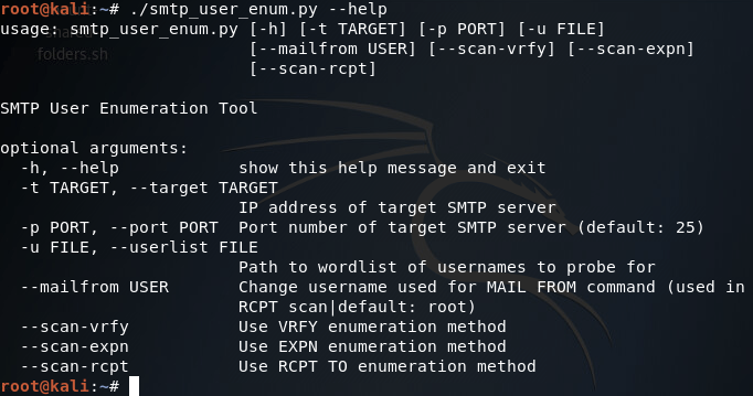
Our help page is looking good! Before we continue with this enumeration however we’ll need to build a small list of usernames. I’ll be using the cat command in the Kali CLI for this purpose:
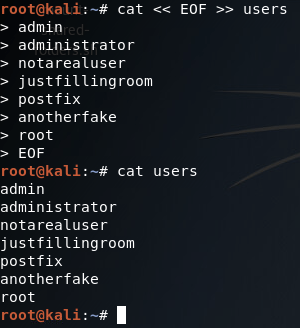
Alright, now we’ve got our list of usernames stored under a file named users. Now that we’ve got that squared away, we can begin testing our different scan types, of which we’ll be starting with the VRFY method:
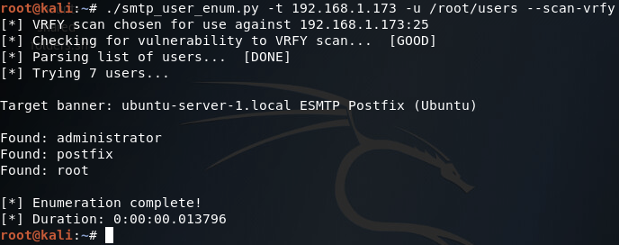
There we go! Our script works! Now let’s move on and test the EXPN scan method:

Our script tells us here that this target is not vulnerable to this type of scan method, which is true (I tried it manually with a telnet session and the command is unrecognized). Finally, we have our RCPT TO method:
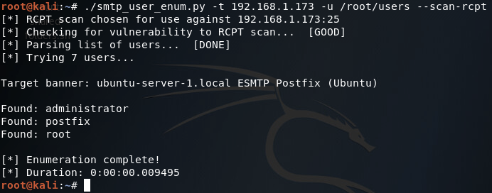
There it is, two of our three scan methods work on this target. Hopefully this helped you learn more about SMTP user enumeration (it definitely helped me), and you can expect to see more home-cooked scripts in the near future!
(Note: just in case you missed the link earlier, the script can be found here.)
Maintaining Access Part 2: A Deeper Look at C2
Welcome back my fellow hackers! In the last lesson on maintaining access we discussed the bare bones concepts of what it means to maintain access and why it is important. Then we went on to install a backdoor in a Windows 7 Pro VM. This time we won’t be installing any backdoors (although I did figure out the privilege issue we had last time), but we’ll be taking a deeper look at C2. First we’ll define what C2 is, then we’ll go into detail on what makes a good C2 infrastructure.
Defining C2
C2 (otherwise written as C&C) is shorthand for Command and Control. C2 is the infrastructure that allows us persistent access to our targets. There are a number of qualities that a good C2 infrastructure should have, and we will also be defining and reviewing those within this lesson.
For those of you who are in penetration testing or looking to get into it, I should inform you that C2 is not always required. In fact, in some instances, C2 is out-of-scope. This means that the customer that hired you to perform the penetration test does not want you leaving backdoors and C2 infrastructure all over the place. Not only could this cause problems between you and the customer, it could end up in problems between you and the law (and trust me, it’s much better to stay on thisside of a cell). So, make sure you ask your customer or a representative of your customer about the scope of your penetration test. Now that we’ve got that out of the way, let’s talk about what qualities make up a C2 infrastructure.
Basic C2 Infrastructure Qualities
There are quite a few qualities that make up a proper C2 infrastructure. As we review these qualities, I’ll describe them in better detail and review why they are important to our overall C2 effectiveness.
- Remote file system access – Our C2 infrastructure should allow us access to the file systems of all the victims that are under our influence. This includes the ability to download/upload files, move files, manage permissions, and all the other file system operations that we need to make our access persistent.
- Remote command execution – Our infrastructure should allow us to execute commands on any given victim. This is a very basic requirement for C2 and does not require a deep explanation.
- Stealth – When it comes to stealth, our infrastructure should be able to slip past any IDS/IPS or firewall that the traffic must flow through. This can be accomplished by disguising our data to look legitimate, such as a covert DNS channel. There are a number of protocols that we can use to hide data, and we’ll get to them in due time.
- Fault tolerance – Our C2 client or agent (the software deployed on the victim) should be able to re-connect to our infrastructure automatically in the event of a network outage or other disruption.
- Persistence – This one is pretty obvious, our C2 agent needs to be able to survive reboots and be persistent on the victim machine.
- Secure communications – The data flowing back and forth between our victims and our infrastructure should not only be disguised, but encrypted. This means that we should encrypt the data before packing it into the disguising packet. This way even if packets from our C2 infrastructure are captured, the data packed within cannot be read without first finding or cracking the encryption key.
That does it for this article, next time we’ll be taking a more advanced look at C2 infrastructure and what technologies we can incorporate into it to make it more suitable. By the end of this series I’d like to be able to script our own C2 infrastructure and agent using Python. This infrastructure will include all the qualities we reviewed here (and hopefully more). See you then!
Networking Basics: The OSI Model
Hello my fellow hackers! Today we’re going to be introducing a topic we should’ve covered long ago, networking. Having an understanding of networking gives us a better understanding of how computers interact with each other. If we understand how these systems communicate over the network, we can better manipulate parts of the network to our advantage. Things such as routers and switches allow us to reach other parts of the network, and learning to manipulate such devices could allow for greater access to the network as a whole. The first couple of articles in this series will be all about the basics. We’ll start here with the OSI model, and work our way up. Once we’ve covered the OSI model, we’ll begin to discuss different network protocols in depth, exploring what they do, and how to exploit them. So, without further adieu, let’s talk about the OSI model!
The OSI Model
The OSI model is a model that breaks down network communication into seven layers. Each layer represents another set of functionalities that are used to get data from point A to point B.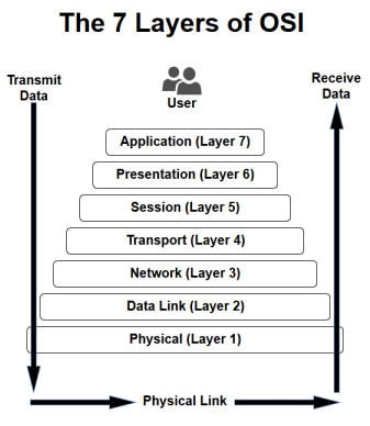 The act of data moving up and down the layers of the OSI model is known as encapsulation and decapsulation. Data being encapsulated moves down the OSI model, while data being decapsulated moves up the OSI model. This representation makes the most sense when analysed from the bottom up, so that what we’ll do.
Layer 1 (Physical Layer)
Layer 1, the physical layer, is very simple. The physical layer is the actual media that the data moves across. Whether it be fiber optics or standard ethernet, the physical layer is the physical media on which our data is moving. For an example of a layer 1 networking device, we’ll take a look at a long out-dated piece of networking technology, the hub.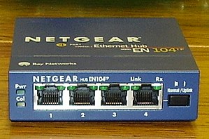 A hub is a very old device that was originally meant to create small LANs. It works by listening for the electric pulses coming into any port, and replicates those electrical pulses out all other ports, effectively passing the data. Since it replicates all pulses out all other ports, this is considered a layer 1 device.
 A hub is a very old device that was originally meant to create small LANs. It works by listening for the electric pulses coming into any port, and replicates those electrical pulses out all other ports, effectively passing the data. Since it replicates all pulses out all other ports, this is considered a layer 1 device.
Layer 2 (Data Link Layer)
Since layer 1 is the physical media, it’s easy to think of layer 2 as a sort of point to point connection. A single node on a network connects to another node, fragmenting, transmitting, and reassembling data as it is passed through the physical layer. The above networking device is a switch. It is primarily used to provide access to the network for the hosts. A switch may serve the same basic functions as a hub, but it’s much smarter in the way it goes about it. Instead of replicating data out all ports, switches send data to the port they are destined for. Imagine it like this: if our NIC connecting to the switch port is layer 2, then the switch can look at all the “point to point” connections it has to decide where data should go. This is what classifies the switch as a layer 2 device.
 The above networking device is a switch. It is primarily used to provide access to the network for the hosts. A switch may serve the same basic functions as a hub, but it’s much smarter in the way it goes about it. Instead of replicating data out all ports, switches send data to the port they are destined for. Imagine it like this: if our NIC connecting to the switch port is layer 2, then the switch can look at all the “point to point” connections it has to decide where data should go. This is what classifies the switch as a layer 2 device.
Layer 3 (Network Layer)
So, if our layer 2 is a set of point to point connections, our layer 3 can be thought of as the functionality that allows us to send data to and from these groups of connections. The above device is a router, which is used for routing information between networks. Here at layer 3, IP addresses are used to identify nodes on a network (at layer 2, a MAC or burnt-in address is used). Since IP can be used to represent a node on a network, routers generally have more than 1 IP address and reside on more than 1 network. This allows them to pass data between networks, such as a home network and an ISP network.
 The above device is a router, which is used for routing information between networks. Here at layer 3, IP addresses are used to identify nodes on a network (at layer 2, a MAC or burnt-in address is used). Since IP can be used to represent a node on a network, routers generally have more than 1 IP address and reside on more than 1 network. This allows them to pass data between networks, such as a home network and an ISP network.
Layer 4 (Transport Layer)
Layer 4 and above gets slightly different than the other layers. Yes, there are devices that operate at layer 4, such as some stateful firewalls, but most of the layer 4 functionality relies on the TCP/IP stack which is installed on all systems that access the network. The transport layer is in charge of just that, transport. There are two main protocols that live at layer 4, TCP and UDP. At this layer port numbers are used to mark where to send data to. A port in this instance is a logical interface on a computer that can either create or receive connections. For example, the SSH service runs on port22.
Layers 5 and 6 (Session and Presentation Layers)
Layers 5 is responsible for controlling connections between systems. Not only does it start them, but it also manages and terminates them. The presentation layer on the other hand is used to convert data back and forth between being machine readable and human readable.
Layer 7 (Application Layer)
Layer 7 is the final layer of our OSI model. The application layer is just that, the application that the data being encapsulated/decapsulated serves. Whether it be DHCP, HTTP, or FTP, the data within is considered application layer data.
That does it for this one! Next time we’ll be focusing more on the layers’ roles in a network, rather than their definitions. Also, we’ll be reviewing another model in the near future, the TCP/IP model. By the end of this series we should be able to look around a network and identify what the infrastructure looks like.
Next up, we’re going to be talking about a few protocols, ARP, IP, and TCP. Understanding these protocols will give us a basis for learning about LANs, which is an important first step in networking. We’ll start with ARP, a layer 2 (data link) protocol. Then, we’ll talk about IP and TCP, protocols resting at layers 3 and 4 respectively.
Understanding ARP at Layer 2
So, to understand ARP, we need to first discuss how computers connect to an Ethernet network. Computers interface to the network with their NIC (network interface card). This card is connected to the RJ-45 (Ethernet) plug on a system.
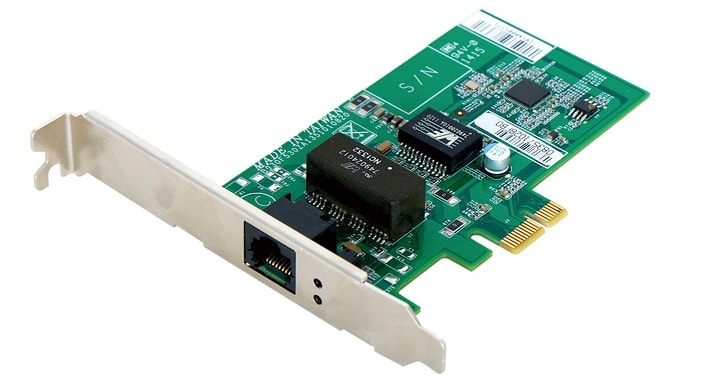 This NIC has an address on it already. This address is known as the MAC address, and its “burned” into the NIC. These MAC address are 48 bits in length, the first 24 of which are the OUI (organizationally unique identifier) which identifies what manufacturer made the NIC.
Now that we have that, let’s discuss ARP (address resolution protocol). ARP is used to resolve an IP address to a MAC address. For instance, if we have an FTP sever on our LAN, our system would use ARP to determine the MAC address of the server NIC so we can contact it on the LAN. Here’s a diagram of how this happens:
ARP simply resolves IP addresses to MAC addresses for communication over LAN. If we open up wireshark, we should be able to see the ARP traffic coming to and from our system:
Understanding IP and TCP
IP (internet protocol) is what allows us to encapsulate data to be transported over layer 3, which sounds fairly redundant but is still an important thing to remember. IP also allows us to give, maintain, and route between IP addresses and address ranges, which grants us the ability to segregate networks logically without have to separate them physically.
TCP is a transport layer protocol that is used to reliably send data from point A to point B. There are a couple protocols which transport our data (TCP and UDP specifically), and they differ from each other widely. For now we’ll only be covering TCP. TCP uses port numbers to differentiate services running on a system, such as port 80 and 443, for HTTP and HTTPS. When TCP attempts to make a connection, a handshake occurs. This is known as the TCP three-way handshake, and looks like this:
It starts with a TCP packet marked with the SYN flag (SYN is short for synchronize). If the destination device has a service running on that port that is accepting connections, it will respond with another packet marked with the SYN and ACK (acknowledge) flags (a SYN in response to ours, with an ACK to confirm its in response to us). The handshake ends with us sending a packet marked with the ACK flag to the destination device to acknowledge their SYN-ACK.
Once the handshake is complete, our connection is considered established until it is dropped or terminated by either side. This connection can now be used to transport data between our two systems reliably. That means that TCP can recognize corrupt or missing data and request a re-transmit of that data.
Putting it Together
Let’s wrap this up with a little hypothetical to bring it all together. Let’s say you have a system on a LAN with a default gateway connected to the internet. If you point your web browser to a site on the internet, your system will first use ARP to find the MAC address of the default gateway (if it doesn’t already know it). Then, once the MAC address is found Ethernet frames will be transmitted across the network to the router, which will be reassembled to reveal that its a TCP SYN packet destined for port 80 of a web server. The router will forward this packet, and all packets related to it, in and out of the LAN. Once the TCP three-way handshake is over, our system will send an HTTP GET request to the web server. Upon receiving the request, the server will response to our system with the requested web page packed as application data in more TCP packets.
There we have it! Hopefully that made some of this click a little better.
So now that we’ve covered ARP, IP, and TCP and covered how these protocols relate to the operation of a LAN. Now, we’re going to be going over a few more protocols, as well as introducing a new model (like the OSI model but a little different). We’ll start with introducing the new model, the TCP/IP model. Then we’ll discuss the DHCP and UDP protocols, their relation to either model, and their role in the network. So, let’s get started!
Understanding the TCP/IP Model
If you remember back to the first article in this series, we talked about the OSI model and its different layers. Well, the TCP/IP model is a lot like that, except that it’s layers are different. Whereas the OSI model has seven layers, the TCP/IP model has four. The TCP/IP model layers are as follows:

The layers of the TCP/IP model, from bottom to top, are comprised of the network interface, network, transport, and application layers. The network interface (sometimes called the network access) layer corresponds to the physical and data link layers of the OSI model. The network and transport layers are the same for both models (the network layer of the TCP/IP model is sometimes referred to as the internet layer). Also, the application layer of the TCP/IP model is equivalent to the session, presentation, and application layers of the OSI model collectively.
There isn’t really a distinct advantage to using one model over the other, but both are used throughout the IT industry, so knowing both can be a big help. Now that we’ve covered the TCP/IP model, let’s get talking about some protocols. We’ll start with UDP, then we’ll discuss DHCP.
Understanding UDP
If you remember the last article, we talked about TCP, a transport protocol used to reliably send and receive data over a network. As we discussed, TCP is reliable and will re-transmit if needed. UDP (user datagram protocol) on the other hand is neither reliable nor does it check the data integrity (integrity is the concept that data should not be damaged or altered, and that we should be able to tell when it has been).
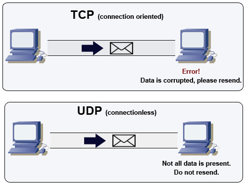
UDP is unreliable, which isn’t necessarily a bad thing. UDP doesn’t even have acknowledgements, which TCP uses in conjunction with checksums to determine if data has been corrupted during delivery. Due to this lack of reliability, UDP is much faster at transmitting data. This makes it perfect for things like voice and video, which are extremely sensitive to delay.
Understanding DHCP
DHCP is a very important protocol to understand, as just about every network makes use of it to a certain degree. DHCP stands for dynamic host configuration protocol, and its in charge of delivering IP information to new hosts joining the network. The information that DHCP provides is the hosts IP address, the subnet mask, the default gateway, and DNS information. To access a LAN, a client must have at least an IP address and a subnet mask.
DHCP relies on the DORA process to deliver IP information to joining hosts. The DORA process consists of discovery, offer, request, and acknowledgement. Its a fairly simple process, first the client sends out a broadcast looking for DHCP servers. Next, if a DHCP server identified the discovery attempt, it will send an offer to the client. Then, the client submits a request to the DHCP server, confirming their accepting of the offer. The DHCP server responds with an acknowledgement and everything is good to go! This protocol allows for easily adding hosts to a network without having to configure IP information for all of them. Its worth noting that DHCP is normally only used for host devices, things such as servers and network infrastructure usually use static IP addressing.
That does it for this one! Hopefully that help reinforce what we learned last time about LAN basics. Next time we’ll introduce routing and switching, and how their respective devices work.
How Hackers Kick Victims Off of Wireless Networks
Hello, my fellow hackers! Today we’re going to be covering a little bit of Wi-Fi hacking. Specifically, we’re going to be learning how to kick other people off of wireless networks, even when we’re not connected to it ourselves! We’re going to be using an external wireless adapter for this, so if you don’t have one, I highly recommend getting one, as it is an essential piece of equipment for hacking Wi-Fi! The wireless adapter I’ll be using for this lesson is the Atheros Ar9271, which is capable of packet injection (injection is a very important feature to have for our wireless adapter). Now that we’ve got all that out of the way, let’s get started!
Step 1: Configure the Wireless Adapter for the Attack
If we’re going to use our wireless adapter for this attack, we’ll need to configure it to do so! First, let’s take an overview look at our current wireless adapter setup:

Now, for this demonstration attack, we’re going to connect our built-in wireless card (wlan0) to the target network. Then, we’ll use our external wireless adapter (wlan1) to kick ourselves off the network. Next, let’s put our external adapter into monitor mode:

First, we use ifconfig to set the interface down. Then, we use iwconfig to change it to monitor mode, then we’ll bring it right back up. Now, when we check the output of iwconfig is shows that our external adapter is in monitor mode. Now that we have our adapter configured for this attack, let’s get to it.
Step 2: Sniff for Target Networks
If we’re going to boot ourselves off a wireless network, we’ll need to identify what network we’re on first! For this, we’ll be using a tool called airodump-ng. This will allow us to view all the wireless networks in our area:

Step 3: Sniff for Victims on the Target Network
Alright, so we have a couple of networks in our vicinity. The network that our built-in adapter is on is NETGEAR89, so let’s do some sniffing specifically for that network. From this information here, we’re going to be using the BSSID and the channel number of the NETGEAR89 network. So, let’s just re-execute airodump-ng and pass it this information:
Now, once we execute this command, we should be able to see information regarding the clients connected to this wireless access point (WAP):

Alright, now that we have this information about the connected clients we can move on to the next part of the attack. (Note: in order for the next part of the attack to work, we need to keep airodump-ng running, so leave this terminal open. I’ve just minimized it to move it out of the way.)
Step 4: Inject Deauthentication Frames into the Target Network
Now that we have the information about the target network, and the clients on said network, we can finally perform our deauthentication attack and boot ourselves off. The tool we’ll be using to inject the deauth frames into the network is aireplay-ng. This is command we’ll use to start aireplay-ng:
Here we specify the deauth attack and tell aireplay-ng to inject only once. We then use the -a flag to give the BSSID of the target network. Ending the command, we specify the client to deauth by using the -c flag followed by the victim’s MAC address. Now, let’s execute this command and wait.
After the injection is finished, we should be able to take a look at our wireless adapters and see that we are no longer connected to a wireless network:
There we have it. After our deauth attack, we can see that our PCI (internal) wireless adapter has been disconnected from the wireless network, we did it! This is only the beginning of Wi-Fi hacking here on HackingLoops. In the near future, we’ll be attempting to build our own versions of the tools we used here, so we can develop a better understanding of how these tools works. When we build these tools, we’ll be using Scapy and Python, so if you haven’t read our articles on those topics, I recommend doing so!

No comments:
Post a Comment